


Function Description:
1. Power Input Source:220VAC(or 110VAC)/50Hz/3A/1F。
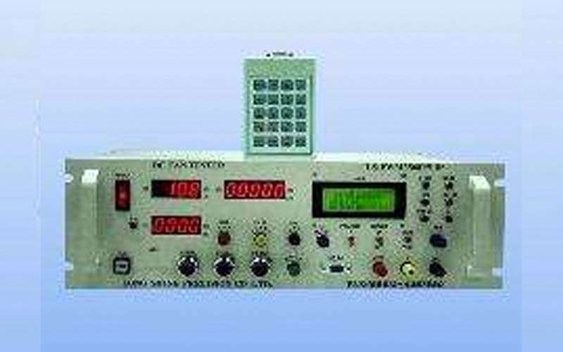
2. Volts-meter(Volts):Using 3-1/2 digits LED to display 0~50.0Vdc voltage.
3. Amps-meter(mA):Using 3-1/2 digits LED to display 0~4999mA current.
4. Tachometer (RPM):Using 5 digits LED to display the revolution( speed:100~49999rpm) of dc fan.
5. The range of output voltage :0.0~50.0Vdc (resolution:0.1volt)
6. Typical output current: 0~4500mA @ instant maxmum output current :4999mA
7. With short-circuits protection circuits and function, and when the output terminals occur short-circuits with15Sec. , it will automatically trip to safety mode
8. Usage range: 2 Terminals /3 Terminals / Temperature control and PWM dc cooling fan.
9. The function and specification of PWM dc cooling fan tester is following as :
9-1. There are eight testing steps in the different setting conditions of frequency(Hz)and dutycycle(%)of PWM output.
9-2. The range of Frequency: 10Hz~ 99.999KHz,resolution: @Hz range: 1Hz; @KHz range:0.001KHz The range of Dutycycle:1~100%,Duty Cycle resolution: Under1 KHz output is below 1%,
above 1 KHz output is below 10%.
9-3. There are 3 type ( P1、P2、P3)of PWM output mode in PO-TYPE to choice
9-4. There are 4type PWM output voltage of PO-SOURCE with 3.3V、5V、12V、+VCC to choice
9-5. There is a MODE(2T/3T/EXT) to detect the revolution of dc cooling fan. It could choice internal mode 2T pick-up revolution signal by current waveform /3T pick-up signal revolution by output of FG terminal or external mode by pick-up revolution signal of photosensor (The photosensor and jigger post is a option accessories)
10.The items of setting parameter for testing:(To input the setting parameter by keyboard and show the testing reports or adjudgement results by liquid crystal display).
The setting parameter for testing is following as:
(a).The delay time:the sampling time for testing(0~99Sec.)
(b).The lower/upper limiting setting value of the dissipation current (0~4999mA)
(c).The lower/upper limiting setting value of the revolution (100~49999rpm)
(d).The frequency setting value: 10Hz~ 99.999KHz
(e).The dutycycle setting value: 1~100%.
11.There is 3 voltage-output volumes in the panel
V1- Adj.: It is aim to set low voltage starting test of dc cooling fan (typical :about 0.6*(5V, 12V, 24V,or 48V))
V2- Adj.: It is aim to set the low voltage test of temperature control cooling fan (below 5V, 12V, 24V,or 48V) or pwm step1~step4 test
V3- Adj.: It is aim to set the rating voltage test of dc cooling fan (over 1.2*(5V, 12V, 24V,or 48V))or pwm step5~step8 test
The tester is with a function of output voltage soft starting in testing to protect dc cooling fan and dc power supply system
12. Testing results: to diplay the testing data and show the results by the OK/NG indicating lamp。
13. There is a TYPE (A/B/C )to choice the proper 2T dc cooling fan to test and detect the revolution. It could select TYPE A for 2T universal type(near100~499mA) dc cooling fan ;TYPE B for 2T lower dissipation current (near50~100mA)dc cooling fan; TYPC for 2T the lowest dissipation current (near25~50mA)dc cooling fan (.internal mode 2T pick-up revolution signal by current waveform. external mode by pick-up revolution signal of photosensor. (The photosensor and jigger post is a option accessories)
14. There are with 50 models data memories and one model with a lot of testing parameters memories of dc cooling fan in the tester.
15. . There is a (S/A/P) TEST MODE to test the revolution of dc cooling fan.It could select S MODE to test
2T /3T dc cooling fan by V1- Adj. to set low voltage starting test and pick-up revolution signal by current
waveform /3T pick-up signal revolution by output of FG terminal or external mode by pick-up revolution
signal of photosensor (The photosensor and jigger post is a option accessories)
